The empty lip balm tube set differs from other lip balm products on the market primarily in its purpose and usage.
Here are some key comparisons:
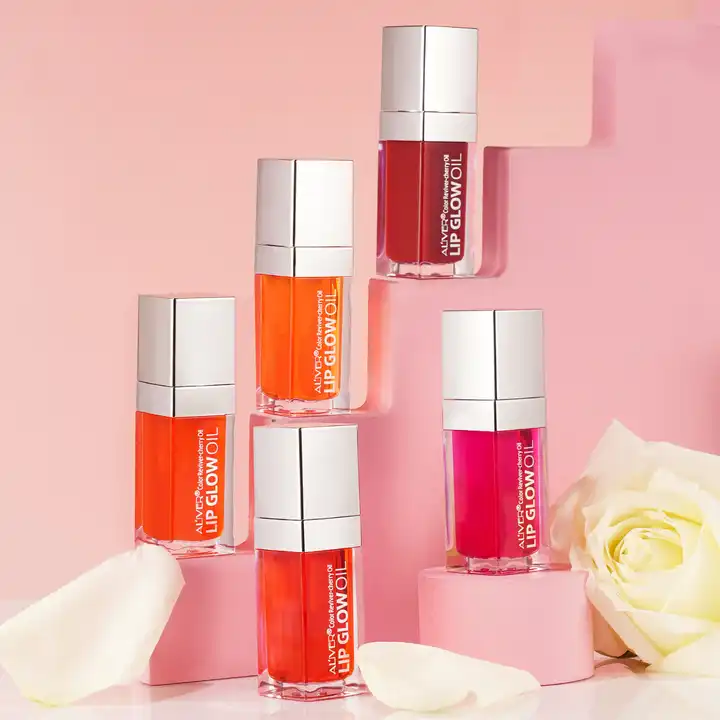
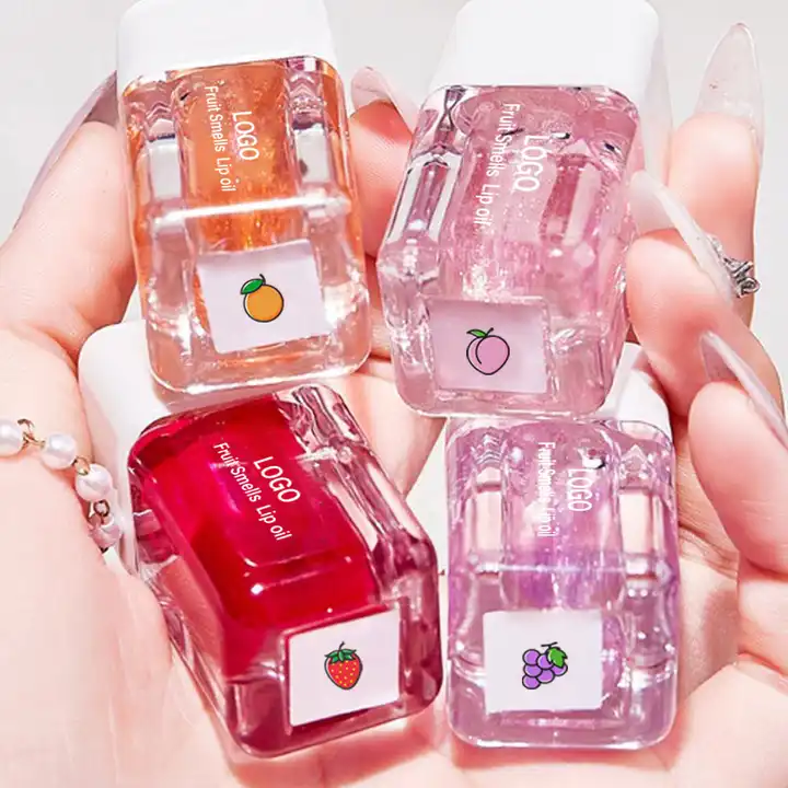
- Customization and Personalization: The empty lip balm tube set allows users to create their own custom lip balm formulations by filling the empty tubes with their preferred ingredients, such as oils, butters, waxes, and flavors. This level of customization is not typically available with pre-filled lip balm products on the market, which come in standard formulations and flavors.
- Flexibility in Ingredients: With the empty lip balm tube set, users have the flexibility to choose the specific ingredients they want to include in their lip balm formulations, allowing for greater control over factors such as texture, scent, flavor, and therapeutic properties. This level of control is not possible with pre-made lip balm products, which may contain a fixed set of ingredients chosen by the manufacturer.
- Cost-Effectiveness: The empty lip balm tube set may offer cost savings in the long run, as users can purchase bulk quantities of empty tubes and fill them with their own formulations, which may be more economical compared to purchasing individual pre-filled lip balm products. This can be particularly beneficial for individuals who use lip balm frequently or prefer to have multiple customized options available.
- Freshness and Quality: By filling the empty lip balm tubes with freshly made formulations, users can ensure the freshness and quality of their lip balm products. empty lip balm tube This is especially important for those who prioritize using natural or organic ingredients and want to avoid preservatives or additives commonly found in commercial lip balm products.
- DIY Experience: The empty lip balm tube set offers a DIY (do-it-yourself) experience, allowing users to engage in a fun and creative activity of making their own lip balm products. This can be enjoyable for individuals who appreciate crafting and personalizing their skincare routines.
- Educational Opportunity: Using the empty lip balm tube set provides an educational opportunity for users to learn more about the ingredients used in lip balm formulations, their properties, and their effects on the skin. This hands-on experience can deepen users’ understanding of skincare ingredients and empower them to make informed choices about their beauty products.
Overall, while the empty lip balm tube set may require more effort and involvement compared to pre-made lip balm products, it offers unique advantages in terms of customization, cost-effectiveness, freshness, and DIY experience. Users who value these benefits may prefer the empty lip balm tube set as a customizable and personalized option for their lip care needs.